BREATHABILITY TEST
The Differential Pressure or Breathability test is the direct measure of the respiratory resistance provided by the mask, evaluated as pressure drop at fixed flow, and it is thus correlated to the effort required by the wearer in order to breath with conventional inhalation/exhalation rates. Taking advantage of the uniformity of the surgical mask, the tests are executed on a representative section, a circular sample of 25 mm of diameter (i.e. 4.91 cm2 of area), in which the pressure drop need to be measured when impacted by 8 L/min air flow;
Such test is of paramount importance not only for the respiratory effort for the wearer, but also because, unlike respirators (personal protective equipment, PPE), surgical masks do not contain specific element that provide a good adhesion with the face, and thus the sealing of the equipment is poor. Hence, if the resistance to the air flow caused by the masks is too high, a fraction of the air passes through the boundaries instead that through the mask, reducing the protection offered by the device.
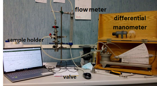
Figure 1 reports the layout of the test rig set-up in our laboratory in which one can distinguish the sample holder, a U-tube manometer (maximum reading 2 kPa, accuracy 1 Pa), a flow meter (range 0-500 L/h) and a regulation valve.
In the apparatus set-up during the emergency time, two different configurations have been prepared, one according to the standard norm, in which the air flow (and thus the pressure difference) is generated by a vacuum pump that pulls air from the section downstream to the mask sample, with upstream section connected to the atmosphere. A second configuration considers the upstream compartment in slight overpressure with compressed air and with the downstream sections at atmospheric pressure. Relevantly, no differences have been observed in the resulting delta p measured at the inspected flow rates, so the latter one has been considered in the light of a slightly easier set-up and the absence of region in the test rig with pressure under vacuum, thus ruling out any possible infiltration from the external air.
In brief, the compressed air is fed to the apparatus and its flow rate is controlled by a dedicated valve and by means of an analogic flowmeter. The sample holder is composed by two stainless steel T-pipes, having an internal diameter of 25 mm and tri-clamp connections at all the extremities, used, as represented in the figure for the connections with the differential manometer.
The samples are prepared by punching with a hollow cutter (25 mm diameter) the prototype mask in different positions. Then, after appropriate conditioning for at least 4 h at 85% R.H. at room temperature (obtained by potassium chlorine KCl supersaturated solutions [[i],[ii]] in a closed box), the samples are placed between the clamp connections of the two tubes and sealed with flat, rubber ring gaskets with an internal diameter of 25 mm, placed above and below the specimen to ensure tightness and the correct sample cross-sectional area.
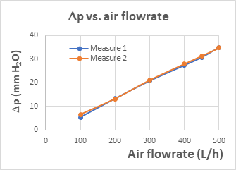
The experimental procedure developed in order to minimize the experimental error and to ensure the repeatability of the test considers the measure of the pressure drop at multiple flow rates, namely 100, 200, 300, 400, 450, 500 L/h at least twice per each specimen. A linear correlation is typically detected, and the slope allowed the determination of the pressure difference at 8 L/min (480 L/h). The final value reported for each specimen is the arithmetic mean of the different measurements (at list two), after its division by sample area, as indicated in the norm.
[i] Standard Practice for Maintaining Constant Relative Humidity by Means of Aqueous Solutions, ASTM E104 – 02 (2012), ASTM International, West Conshohocken, PA 19428-2959. United States.
[ii] L. Greenspan, Humidity Fixed Points of Binary Saturated Aqueous Solutions, J. Res. Nat. Bureau Stand. A Phys. Chem. 81 (1977) 89-96.